ECU DEVELOPMENT

Electric Vehicle Powertrain Control Unit

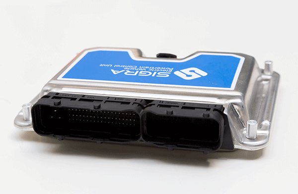
SIGRA Electric Vehicle Power Control Unit manages the complete powertrain. The control unit features a powerful microcontroller designed for automotive safety applications to provide high performance. This control unit utilizes MATLAB/Simulink based software development process to speed up the algorithm development by using automatic code and document generation.

The flexible hardware design allows for easy customisation of functionalitiesas per customer specifications.

We deliver libraries and a package of MATLAB/Simulink toolboxes to interface with all I/Os and calibration tool with access to all signals.

SIGRA Powertrain ECU in action

Quick Overview

  • Designed for 12/24V systems
  • Compact housing
  • Customised features and applications
  • Universal calibration and monitoring

Application

  • Drive management
  • Communication with the BMS
  • AC charging communication and monitoring
  • DC charging monitoring
  • Communication with the on-board charger
  • Communication with the power steering control unit
  • Communication with instrument cluster unit and infotainment system
  • Cabin climate control management
  • Control of the Auxiliary MCU
  • Communication with DC-DC charger
  • Universal calibration and monitoring
  • System diagnostics

Individuality

SIGRA provides the option to include new functionalities and applications as per our customers need. We provide TAPAS universal measurement and calibration protocol for calibrating the powertrain control unit.

Flexibility

We provide the option to run software code on the powertrain control unit that has been developed by our customers. This feature can run in parallel to all the powertrain control unit functionalities.

Technical Specifications

  • Software Specifications
  • Algorithm development environment in MATLAB/Simulink
  • Support for generating executables that include algorithms, device - drivers and real - time operating system
  • Full access to I/Os
  • Full read access of all signals
  • Real time calibration
  • SW download via TAPAS calibration tool
  • Calibration and measurements interface via CAN
  • Hardware Specifications
  • Aluminium housing
  • 121 pin connector
  • Power supply
  • CPU
  • 3 CAN
  • 1 UART
  • SPI
  • 32 Digital Inputs
  • 10 Analog Inputs
  • 20 Digital outputs
  • 6 PWM outputs –correlated (optional)
  • 4 PWM inputs